Configuring ports
This section covers configuration of front panel ports. Port related functions
are accessed through the port command. Without the config modifier these
commands are limited to showing the current port status. With the config
modifier it is possible to change settings on the port. Ports are analogous
to interfaces on other vendor's products.
All of the commands shown in this section can be entered either on a single line or from within the port modal state. To enter the modal state for a given port, simply enter:
admin@N3550-F> config port A1
admin@N3550-F(config-port:A1)>
When in the port modal state, it is possible to omit the config port A1
prefix from commands.
The keyword interface can be used instead of port anywhere on the system, for example:
admin@N3550-F> show interface A1
Version
Using interface instead of port requires version 1.10.0 or later
Naming conventions
The Cisco Nexus 3550-F Fusion (formerly ExaLINK Fusion) has three front panel line card bays. From left to right, these bays are referred to as A, B and C. Ports are referenced by their line card bay, followed by the port number on the line card. As an example, port number 1 in line card bay A is referred to as port A1.
A port can be given an alias, which is interchangable with its positional name. This is a convenient way to associate ports with devices on the network. For example, if port A1 was connected to an exchange, an alias could be configured as follows:
admin@N3550-F> config port A1 alias exchange
Alias set on port A1
An alias can be removed using the no form of the alias command:
admin@N3550-F> config port A1 no alias
Alias removed on port A1
If a more detailed description of the port is required a port description can be set. For example to add a description to the exchange facing port we described above:
admin@N3550-F> config port A1 description "Primary exchange order line"
Description set on port A1
Port speed
The Nexus 3550-F supports both 1GbE and 10GbE standards. The speed of a port should be set such that it matches the speed of the device that is connected to it. Even if a port is operating in a pure layer 1 configuration, it should still be configured to the correct speed as this will ensure optimal signal recovery.
To configure the speed of a port, use the speed command as shown:
admin@N3550-F> config port A1 speed 1000
Port A1 speed set to 1000
The speed is set in megabits per second (Mbps) and can be either 1000 or 10000.
Port details
Detailed port statistics are available on all ports, and can be accessed with the
show command. For example, to show detailed statistics on port A1:
admin@N3550-F> show port A1
Port name          : A1
Alias              : exchange
Description        : Primary exchange order line
Speed              : 1 Gbps
Autonegotiation    : enabled (setting applies for switch and mux ports only)
LLDP agent         : receive only
Link generator     : disabled
Status             : SFP present, signal detected

Vendor name        : OEM
Vendor OUI         : 00-90-65
Part number        : SFP-10G-SR
Revision           : 02
Connector type     : LC
Transceiver codes  : 10G Ethernet: 10G Base-SR
Serial encoding    : 64B/66B
Bit rate (nominal) : 10300 Mbps
Laser wavelength   : 850 nm

Serial number      : CSSR1405880
Date code          : 140501

Temperature        : 37.6836 C
Supply voltage     : 3.3058 V
Tx bias current    : 3.751 mA
Tx output power    : 0.61 mW (-2.1 dBm)
Rx input power     : 0.44 mW (-3.6 dBm)

CDR lock           : yes

Link status        : up
Link up/down count : 3
Autoneg status     : complete
Packets received   : 373
Bytes received     : 223300
Receive errors     : 0
Runt frames        : 0
Pause frames       : 0
Packets sent       : 82
Bytes sent         : 64104
Errors sent:       : 0
In the printout above the following statistics are present:
- The
port name,alias, anddescriptionmap to the settings described in the port name section. - The
speedfield shows the currently configured port speed. - The
autonegotiationfield shows whether autonegotiation on 1GbE is turned on. This setting does not apply if the port is operating in layer 1 mode. - The
statusfield shows whether an SFP or cable is present, and whether that SFP is reporting a signal present. - The details of the installed SFP or cable are available in the fields from
vendor namethrough toRx input power. - The state of the clock and data recovery circuitry on the line card are reported
in the
CDR lockfield. When a valid 1GbE or 10GbE physical layer signal is present, this field will reportyes, otherwise it reportsno. - When an FPGA module is present, the
link statusfield shows whether the MAC within the FPGA has acquired a lock to the incoming data stream. - The
Link up/down countshows the number of times the link has gone up & down, which can be useful in debugging connection issues. Autoneg statusshows the current status of 1GbE Autonegotiation.- Packet and byte sent and receive count statistics.
Port details, verbose
Version
This requires version 1.11.0 or later
A more verbose counter view can be shown by adding the detailed keyword, for example:
admin@N3550-F> show port A1 detailed
Port name            : A1
...
...
CDR lock             : yes

Link status          : up
Link up/down count   : 3
Autoneg status       : complete
Packets received     : 373
 - Unicast           : 63
 - Multicast         : 310
 - Broadcast         : 0
 - 64B frames        : 0
 - 65-127B frames    : 0
 - 128-255B frames   : 373
 - 256-511B frames   : 0
 - 512-1023B frames  : 0
 - 1024-1518B frames : 0
 - 1519-1922B frames : 0
Bytes received       : 223300
Receive errors       : 0
Runt frames          : 0
Pause frames         : 0
Packets sent         : 82
 - Unicast           : 82
 - Multicast         : 0
 - Broadcast         : 0
 - 64B frames        : 0
 - 65-127B frames    : 0
 - 128-255B frames   : 0
 - 256-511B frames   : 82
 - 512-1023B frames  : 0
 - 1024-1518B frames : 0
 - 1519-1922B frames : 0
Bytes sent           : 64104
Errors sent:         : 0
Tip
If the source of data for a port is a layer 1 path, then the source port
is shown in the output of show port. For example, consider the case where
port B1 and C1 were patched together, the output of show port B1
would show:
admin@N3550-F> show port B1
...
...
Layer 1 Source     : C1, link status up
Note this feature requires version 1.11.0 or later.
Resetting Port Counters
The port statistics counters can be reset.
admin@N3550-F> configure port A1 reset counters
Port A1 counters reset
Port overview
In addition to the detailed output available for all ports, an overview can be obtained
using the generic show port command without specifying a port. This command will
show a summary of all ports installed in the device along with its current status.
admin@N3550-F> show port
Port Status           Description
---- ---------------- ---------------------------
A1   up               Primary exchange order line
A2   up
A3   down (no signal)
A4   disabled
A5   disabled
A6   down (no signal)
A7   disabled
A8   up
A9   up
A10  down (no SFP)
A11  disabled
A12  disabled
A13  disabled
A14  disabled
A15  disabled
A16  disabled
DWDM SFP Transmission Tuning
Version
This feature requires version 1.8.0 or later
The Nexus 3550-F supports the configuration of SFF-8690 compliant DWDM tunable SFP connectors through the config port interface, allowing for the stacking of multiple optical signals onto one fibre cable by using wavelength division multiplexers. Configuration is done using the tx-tuning command. It takes one of two parameters: channel or wavelength.
channel can be used to specify a value from a range stored in the SFP:
admin@N3550-F> configure port A1 tx-tuning channel 1
Port A1 tunable transmitter configuration sent to SFP module: channel 1
Alternatively you can use wavelength to specify a value supported by your model. For example:
admin@N3550-F> configure port a1 tx-tuning wavelength 1610
Port A1 tunable transmitter configuration sent to SFP module: wavelength 1610
Simulated Link Generation
Version
This feature requires version 1.10.0 or later.
Before version 1.12.0, this feature must be enabled manually using the link-gen command:
admin@N3550-F(config)> port A1 link-gen
Simulated link generation on port A1 enabled
In version 1.12.0 and later, this feature is automatically enabled.
A common use for Layer 1 switches is for the distribution of market data. This can be done with patch or tap objects. If only tap objects are used, the link partner providing market data will not detect incoming link (i.e. report the switch interface as down), and as a result may not send traffic.
If a port does not have a source of data, the Nexus 3550-F will generate and transmit link out a particular port, so that the remote end detects link and will bring the interface up. The image below shows a tap of data coming into port A1 to ports B1-B4, and the link generator on port A1 is enabled. This means the device connected to port A1 will detect the link as being up irrespective of what happens to the connections on ports B1-B4.
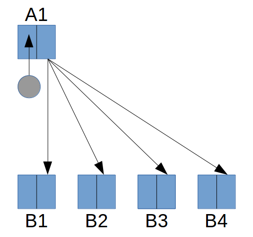
Link generation in use along with taps
Link generation will be enabled when:
- A SFP is plugged in to the port, and
- The port is not part of an object that outputs data to the port
Line Cards that have a Hardware Type of LC10G-02 or LC10G-03 do not support this feature. An FPGA module is not necessary, i.e. this feature is supported on Layer 1 only Nexus 3550-Fs also.
Link generation is only supported at 1G and 10G.
This page was last updated on Feb-19-2021.