Mirror and timestamping - Cisco Nexus 3550-F Fusion HPT
Note
This page describes the operation of mirror objects for the Cisco Nexus 3550-F Fusion HPT (formerly ExaLINK Fusion HPT). For details on the operation of mirror objects for the Cisco Nexus 3550-F Fusion (formerly ExaLINK Fusion), please refer to this page.
The mirror object provides a mechanism for configuring the logging and timestamping functionality within the Nexus 3550-F HPT.
All packets that enter the mirror object are timestamped on arrival at the ingress port to a resolution of 100ps, along with other metadata such as port number and a device ID. This metadata is then appended to the incoming packet and sent to one or more output ports.
The supported port speeds varies depending on the currently selected firmware mode.
The hpt firmware supports 1G and 10G ingress ports, and the hpt-40g firmware supports 10G and 40G ingress ports.
Refer to this section for details on selecting firmware.
Version
Support for 1G and 40G ingress ports requires version 1.12.0 or later.
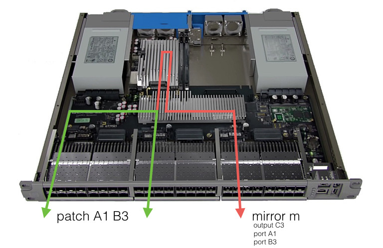
Example use of a mirror, showing port A1 and port B3 mirrored to output port C3.
Creating a mirror
A mirror object is created using the mirror command and giving the object a name. The command must be completed in configuration mode, or prefixed with the configure command:
admin@N3550-F(config)> mirror mymirror
Mirror "mymirror" created
Creating a mirror will place the command line into a config-mirror state.
Note
Only a single mirror object is supported on the Nexus 3550-F HPT.
Input Ports
Note
The Nexus 3550-F HPT supports 40x 10G/1G mirror input ports in hpt firmware mode. In hpt-40g firmware mode 4x 40G + 24x 10G input ports can be used.
The mirror will aggregate and timestamp traffic entering any of its ports. For example, to aggregate all traffic received on ports A1 and B3:
admin@N3550-F(config-mirror:mymirror)> port A1; port B3
Added port "A1" to mirror "mymirror"
Added port "B3" to mirror "mymirror"
Note: It is not possible to explicitly mirror the output of a port using a mirror object, only inputs to ports. In order to take a copy of all traffic leaving a port, it is suggested to use a tap object and tap the output port, or work out what the source port for this output port is, and add the source port to the mirror.
Input ports to a mirror object can also be part of patch or tap objects. For example, the following configuration is supported:
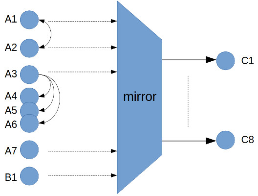
An example of a mirror with a number of inputs also used for patches and taps.
To remove a port from the mirror, use the no form of the commands:
admin@N3550-F(config-mirror:mymirror)> no port A1
Removed port "A1" from mirror "mymirror"
Output Port(s)
One or more output ports needs to be assigned to the mirror object. To add a single output port, use the following command:
admin@N3550-F(config-mirror:mymirror)> output C3
Added output port "C3" to mirror "mymirror"
Note: A port cannot be used for both an input and an output at the same time.
Multiple output ports can be used to share the output load across several ports, and is required in cases where the sustained aggregate input bandwidth is greater than 10Gb/s in order to prevent packet loss. This is done by creating a bond object, adding ports to the bond object, and assigning the bond object to be the mirror output. For example:
admin@N3550-F(config)> bond mybond
Bond "mybond" created
admin@N3550-F(config-bond:mybond)> port C1-C3
Added port "C1" to bond "mybond"
Added port "C2" to bond "mybond"
Added port "C3" to bond "mybond"
admin@N3550-F(config-bond:mybond)> exit
admin@N3550-F(config)> mirror mymirror output mybond
Added output "mybond" to mirror "mymirror"
Note
Up to 8 10G ports can be used for a bonded output.
Removing a mirror
When the mirror object is no longer needed it can be removed with the no form of the mirror command:
admin@N3550-F> config no mirror mymirror
Mirror "mymirror" deleted
Input Buffering Architecture
A multi-layered buffer design is implemented on the Nexus 3550-F HPT to minimize the chance of dropping packets arriving into or traversing the device due to buffer overflow. The following diagram describes this design:
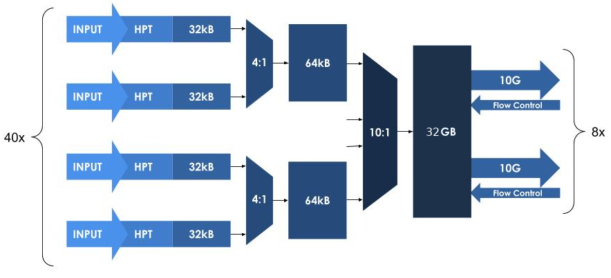
An overview of the buffer architecture used on the Nexus 3550-F HPT.
The show port can be used to see if there have been any drops on a port, for example:
admin@N3550-F> sh port c13
Port name          : C13
Address            : 643F5F8284BC
...
...
Link status        : down
Link up/down count : 0
Packets received   : 0
Bytes received     : 0
Receive errors     : 0
Packets sent       : 0
Bytes sent         : 0
Packets dropped    : 0
Note: By design, packet loss will only ever occur at a port's first input. The packet loss counter will therefore account for all loss for any given port.
The show stats switch command can be used to see how much of the 32GB buffer is being used:
admin@N3550-F> show stats switch
Used memory : 655107840 bytes
Note: This is an instantaneous view of the buffer usage.
Output Format
All frames aggregated through the Nexus 3550-F HPT mirror have a 16 byte trailer appended. This trailer includes the following information:
- Device identifier
- Port identifier
- Timestamp
- Flags
- Recalculated CRC for the whole frame
Note
Runt frames of less than 64 bytes are padded up to 64 bytes before the trailer is added.
Frames longer than 1600 bytes are truncated to 1600 bytes before the trailer is added.
The output frame format of the Nexus 3550-F HPT is as follows:
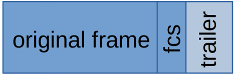
The trailer format is:
| Byte | Description |
|---|---|
| 1 | Device ID |
| 2 | Port ID (Refer Device and Port ID) |
| 3-11 | Timestamp |
| 12 | Flags |
| 13-16 | CRC (FCS) |
As packets flow out of the DDR4 buffers shown in the buffering diagram above, a scheduler is used to select which output port packets should be sent (in the case when multiple output ports are configured). This scheduler will keep the egress bandwidth across these ports even.
An example software for the consumption of traffic coming out of the Nexus 3550-F HPT is available. Please refer to the timestamp-decoder software project for further details.
An example pcap file containing several output packets from a Nexus 3550-F HPT can be downloaded here.
Timestamp ordering
All packets arriving on any single input port are guaranteed to be output in timestamped order. However no guarantee is made between ports.
For example, consider a mirror configuration with a single input port (P1) and a single output port. In this case, if two packets arrive at P1 in the order P1.1, P1.2, then all packets will be output in timestamped order i.e. P1.1, P1.2
Now consider a configuration with 2 input ports (P1 and P2) and a single output port. In this case packets may arrive in order following order P1.1, P2.1, P1.2, P2.2. However, they may be output from the mirror in the following order: P2.1 P2.2 P1.1 P1.2. In this case, the arrival order of all packets on P1 is maintained (P1.1, P1.2), and the arrival order of all packets P2 is also maintained (P2.1, P2.2). However, the relative order of packets between port P1 and P2 has not been maintained.
Consumers of this data that require all packets to be in timestamp order (irrespective of the source port) will need to sort the packets in timestamp order.
Timestamp Format
The timestamp added to each packet is 9 bytes wide. The upper 32 bits are the seconds since epoch, and the lower 40 bits are the fractional seconds. For example, if the 9 byte timestamp is 0x5B7DEEAC_12FBD45A2E, the time is:
0x5B7DEEAC == August 22, 2018 11:15:56 PM
0x12FBD45A2E == (81534409262 * 2^-40) = 0.07415511323597457
In other words, 20180822T231556.07415511323597457
Flow control
The output ports of Nexus 3550-F HPT mirror objects are able to accept IEEE 802.3x pause frames. This flow control signal is issued by some NICs to slow the rate of the incoming traffic. e.g in cases where the capture device cannot keep up with the incoming traffic rate.
Device and Port ID
The device and port ID fields allow a consumer of traffic from the Nexus 3550-F HPT to determine where a packet originated when multiple ports across multiple Nexus 3550-F HPT's are used in an environment. There is a fixed mapping of input port name to the port ID value used. This is:
| Port Name | Port ID |
|---|---|
| A1 | 1 |
| A2 | 2 |
| ... | ... |
| A16 | 16 |
| B1 | 17 |
| B16 | 32 |
| C1 | 33 |
| C16 | 48 |
The device ID is an integer between 0 and 255 can be assigned by the user as follows:
admin@N3550-F(config-mirror:mymirror)> device-id 29
Set device ID to 29 on mirror "m1"
Flags
The following table describes what different bits in the flags field in the trailer format indicate.
| Bit | Flag |
|---|---|
| 0 | Aborted frame |
| 1 | Truncated jumbo frame (larger than 1600B) |
| 2 | Frames dropped on this port (Not yet implemented) |
| 3 | Time synchronization lost (Not yet implemented) |
| 4-7 | Unused |
Important
Accurate time synchronization of the Nexus 3550-F is important when using a mirror with timestamping enabled. Synchronization allows the Nexus 3550-F to provide keyframes that accurately correlate the internal timestamp counter with absolute "wall clock" time. Refer to System Time for details on setting and maintaining accurate time synchronization.
This page was last updated on Feb-19-2021.