Introduction
The Cisco Nexus 3550-F Fusion (formerly ExaLINK Fusion) has a modular architecture that is uniquely configurable. This overview explains the architecture of the Nexus 3550-F and how the user interface exposes this functionality.
The Nexus 3550-F architecture is centered around a dynamically reconfigurable layer 1 switch. The layer 1 switch allows any of its inputs to be dynamically patched or replicated to multiple outputs. Since forwarding happens at layer 1 it involves very little latency overhead and is protocol agnostic.
Each of the three front panel line card bays have 16 dedicated inputs and outputs to the layer 1 switch. The currently available line card includes 16 SFP+ ports that are suitable for 10 GbE and 1GbE operation. Since all three line cards connect directly to the layer 1 switch, the user can create any combination of layer 1 interconnections between front panel ports using patch or tap objects. From left to right, the line card bays are designated A, B and C.
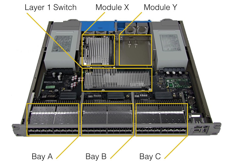
Overview of the Nexus 3550-F architecture.
Also connected to this layer 1 switch are two internal module bays. Both module bays have 48 dedicated input and outputs connected to the layer 1 switch. Any of these 48 inputs or outputs can be dynamically reconfigured to connect directly to any front panel port, or to any input or output on the adjacent module. From left to right, module bays are referred to as X and Y. When ordered with switching or muxing functionality included, bay X will have a FPGA module fitted. When performing switching or muxing, the management interface will automatically route the required signals from the front panel to inputs or outputs on the module bay.
The FPGA module that is included in the mux and switch capable Nexus 3550-Fs can be configured to run different firmware types. At present, three firmware versions are available:
- The
muxfirmware is optimized for aggregation functionality. This firmware can be used to combine up to 47 'downstream' ports into a single upstream port. Up to four 'upstream' ports can be configured with different combinations of downstream ports. Configuration is exposed using the mux object. Upstream ports can also be used as logging and timestamping ports, and can be configured in this mode using the mirror object. - The
switchfirmware performs general purpose layer 2 switching. With this firmware, a 48 port layer 2 switch can be configured using the switch object. Multiple, independent switches can be defined that incorporate any of the front panel ports. The switch firmware can also be used for mux and mirror objects. - The
fastmuxfirmware is optimized for lowest latency 10G aggregation. Currently, only one mux object per FPGA module is supported with capability of aggregating 15 downstream ports into a single upstream port.
The user can change between firmware functions at any time using the command line.
This page was last updated on Feb-19-2021.